DWDM pre-FEC BER alarm is the earliest signal that an optical link is degrading toward a hard failure.
You got the page. A DWDM transponder somewhere in your network is reporting a pre-FEC BER alarm. The link is still up. Traffic is still flowing. But your monitoring system is telling you something has changed on the optical layer, and that something is pointing toward eventual failure if you do not act. This post walks through what a pre-FEC BER alarm actually means, the five real causes ranked by what we see in production, and the right order to troubleshoot so you do not make it worse.
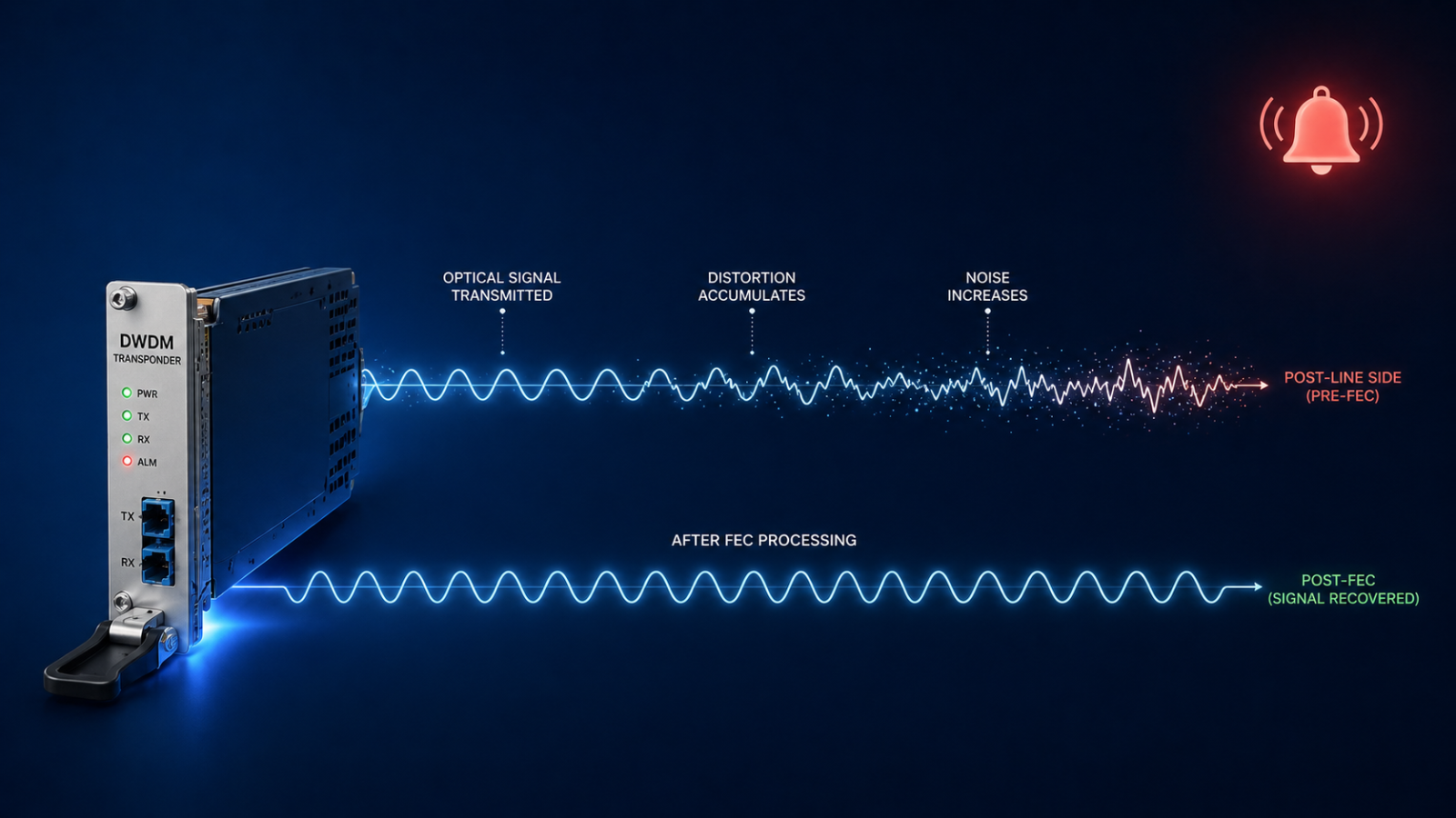
The short version. Pre-FEC BER (forward error correction bit error rate) is the raw error rate measured at the transponder receiver before the FEC engine corrects it. Modern coherent optics correct enormous amounts of error in real time, which is why the link still works even when the alarm fires. The alarm is your early warning system. By the time you see it, the optical path is already degrading, and you typically have hours to days before FEC runs out of margin and traffic actually drops. The good news is that pre-FEC BER alarms are usually fixable without an outage, if you know the order to check things.
The bad news is that the wrong move at this stage, especially the wrong cleaning attempt on a connector, can take a degraded link and make it a hard failure within minutes. So the order matters more than the speed.
What this alarm actually means
Every coherent DWDM transponder uses forward error correction to push more bandwidth down a fiber than the raw signal-to-noise ratio would otherwise allow. The receiver counts errors in the incoming bit stream before correction, calculates a running pre-FEC BER value, and compares it to a configured threshold. When the BER crosses that threshold, the alarm fires.
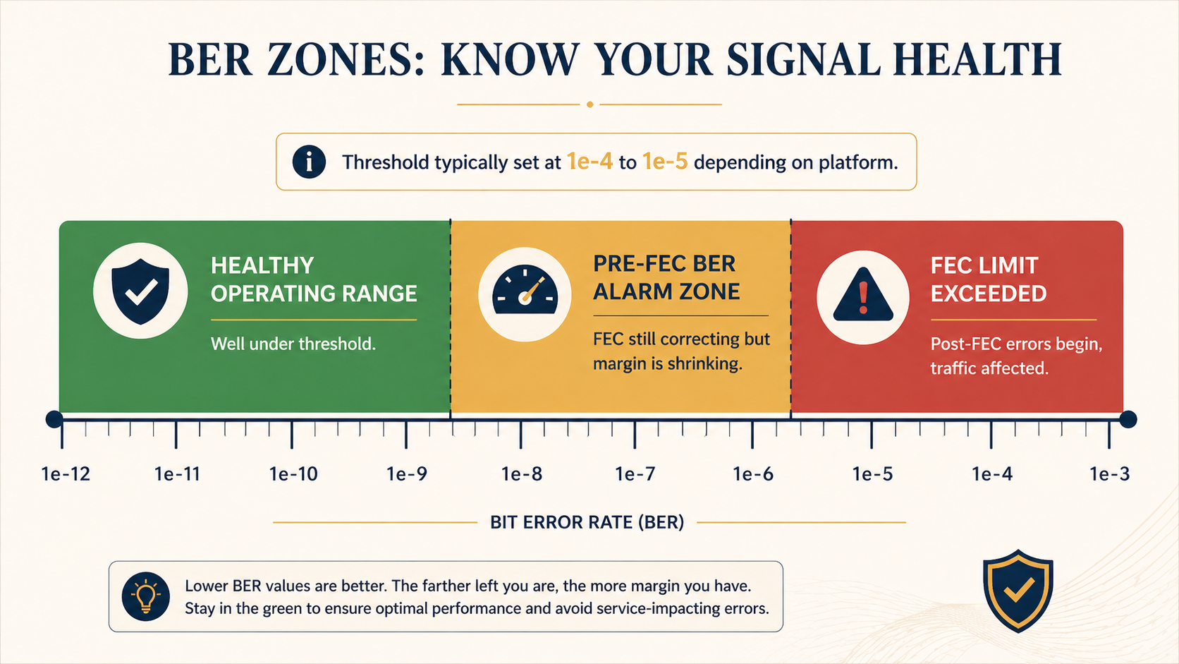
Threshold values vary by platform but typically sit between 1e-4 and 1e-5. That is far above the post-FEC BER you actually deliver to traffic, which on a healthy 100G or 400G coherent link should be near 1e-15 or better, often called error free for practical purposes. The pre-FEC value is the canary, not the customer impact metric.
You will see the alarm in three places. The transponder card or pluggable optic raises a local LED and logs the event. Your DWDM management platform (Ciena MCP, Nokia NSP, Infinera Transcend, Cisco Crosswork, etc.) raises an alarm with the wavelength, span, and current BER value. And your network monitoring system flags the affected service if you have it correlated with the optical layer. If you only have the customer-facing alarm and not the optical one, you will probably be debugging this with much less time on the clock.
Verified against current Ciena, Nokia, and Cisco DWDM platform documentation, accessed April 2026.
The five causes, ranked by what we actually see
Cause one, dirty or damaged connector somewhere on the fiber path, around 40 percent of cases
By far the most common. A speck of dust, a fingerprint, or a microscopic scratch on a connector endface adds optical loss and back reflection, which lowers the OSNR at the receiver and drives BER up. Often the connector was disturbed recently during patch panel work, a fiber move, or a maintenance window.
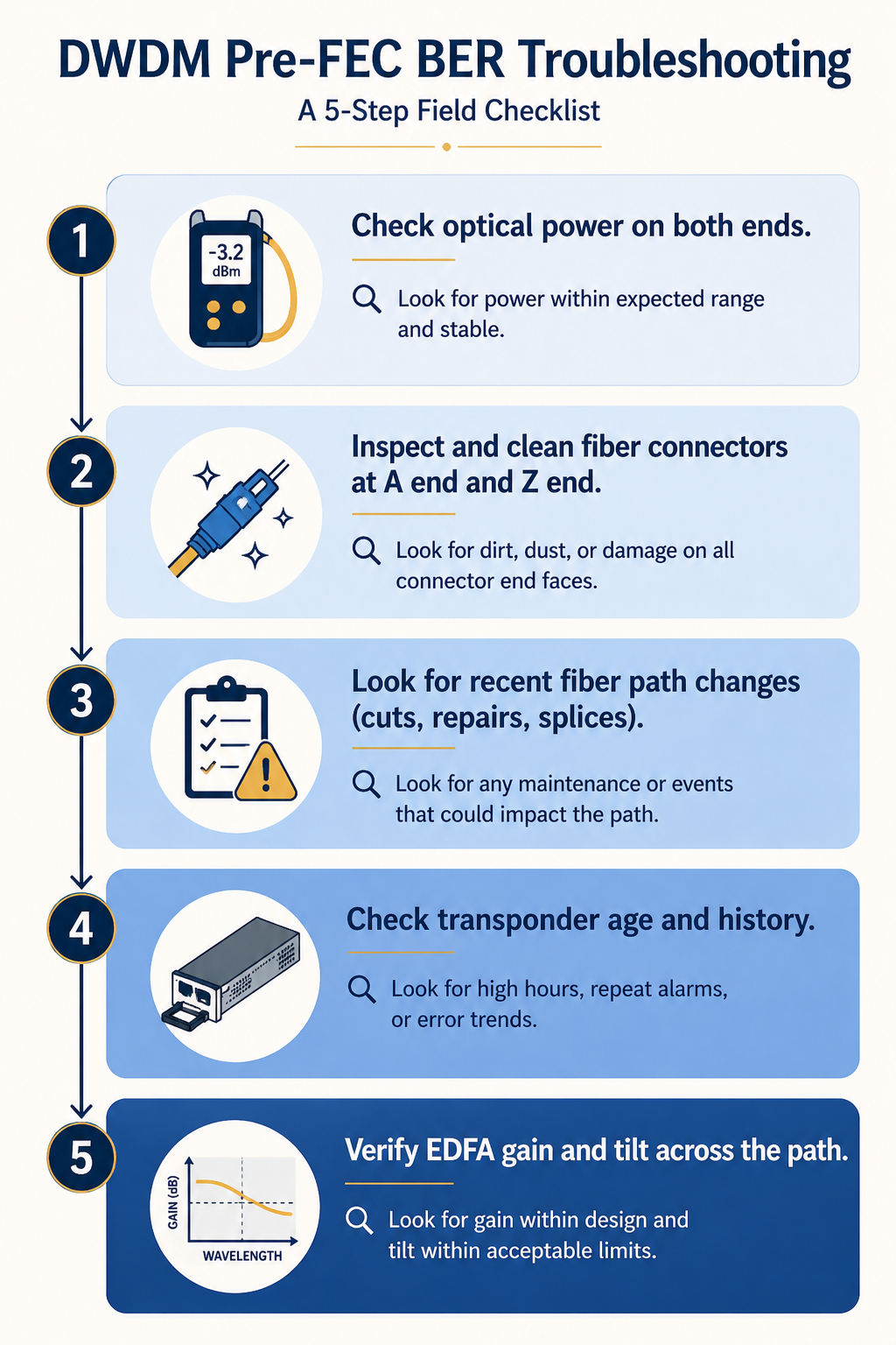
Verify by checking the optical power level at the receiver against the design budget. A drop of 1 to 3 dB from baseline is suspicious. A drop of more than 3 dB strongly indicates a connector issue. Trace the path and inspect each connector with a fiberscope. Do not assume it is clean because it looks clean. Visible inspection at human eye scale tells you nothing about a single mode connector.
Critical: clean in the right order, and use the right tool. A click cleaner on a connector that has a damaged endface can grind the contamination further into the ferrule. Always inspect first, then clean only if dirty, then re-inspect to confirm you did not make it worse.
Cause two, optical power degradation from a bend or stress on the fiber, around 20 percent of cases
Fiber that has been stepped on, pinched in a cable tray, kinked at a panel exit, or stressed by recent rack work. Loss is concentrated at the bend point and may not be on the patch panel itself.
Verify with an OTDR shot from one end. The trace will show a discrete loss event at the bend location. If you do not have an OTDR available immediately, walking the path and visually checking for fiber that does not have natural curvature catches a surprising number of these.
Cause three, aging transponder or pluggable optic, around 15 percent of cases
Coherent optics drift over time. Laser wavelength can shift slightly, modulator bias points move, and DSP performance degrades. After five to seven years in service, even good optics can start running closer to FEC threshold. The give-away is that the BER trends up gradually over weeks, not suddenly, and the optical power at the transmit end is also slightly off baseline.
Verify by comparing the current performance metrics to the original commissioning records. If transmit power has dropped by 1 to 2 dB and BER has climbed gradually, the optic is the suspect. Plan to replace it during a maintenance window. This is the only cause where the fix is hardware swap rather than path remediation.
Cause four, accumulated chromatic dispersion or PMD, around 15 percent of cases
On long haul links, accumulated chromatic dispersion (CD) and polarization mode dispersion (PMD) eat into your OSNR margin. If something has changed on the path (a longer reroute due to a fiber cut, a new amplifier site added, a span change), the CD or PMD budget may have shifted past what the transponder DSP can compensate.
Verify by checking your DWDM management platform for the link’s measured CD and PMD values against the commissioning baseline. Significant changes correlate with path topology changes. Fix is either physical (compensation modules) or operational (reroute back to the original path or accept the new performance baseline).
Cause five, EDFA gain tilt or amplifier issue, around 10 percent of cases
An erbium doped fiber amplifier (EDFA) on the path is producing uneven gain across the C band, so some wavelengths are amplified well and others are not. Often shows up as one or two specific wavelengths alarming while neighbours stay healthy.
Verify by checking per-channel power across the affected wavelength range at each amplifier site. A gain tilt event will show as a slope across the band rather than a single channel issue. Fix is amplifier maintenance or replacement.
What the vendor documentation does not tell you
The vendor docs tell you to check optical power and clean connectors. They do not tell you that the act of cleaning a connector during an active alarm has a non-trivial chance of making things worse if you skip the inspection step. Hard rule, never clean a connector you have not inspected first. About one in twenty alarms we have seen escalated from pre-FEC alarm to total link loss because someone reached for a click cleaner without inspecting the endface.
Also, pre-FEC BER alarms can fire and clear on their own due to environmental factors like temperature changes affecting splice loss in outside plant fiber. A pre-FEC BER that ranges between alarm and clear over a 24 hour cycle may not be a defect, it may be normal day/night thermal variation. The fix is to raise the threshold slightly or to accept the variation rather than chase it.
The architectural fix
Networks that catch BER issues early and act on them have three things in place. First, an OTDR baseline taken at commissioning for every span, stored where the NOC can find it. When BER climbs, comparing the current OTDR shot to the baseline tells you in minutes whether the path has changed. Second, automated trending on pre-FEC BER per wavelength so the NOC sees the slope, not just the threshold crossing. A wavelength climbing slowly toward threshold deserves a planned maintenance ticket weeks before it alarms. Third, a strict connector hygiene policy with documented inspection-before-cleaning workflow, training every NOC technician, and a stocked supply of fiberscopes at every datacenter.
When to escalate
Engage your DWDM platform vendor TAC if BER continues to climb after the fiber path is verified clean and the optical power is within budget. Bring the per-second BER counters from the affected transponder, the optical power readings from both ends, the OTDR baseline and current trace, and the path’s amplifier records. Without that data, vendor TAC cannot help and you will spend hours getting them up to speed.
FAQ
Is a pre-FEC BER alarm service-affecting?
Not directly, no. By design, FEC corrects the errors before they reach the customer payload. The alarm tells you the FEC is working harder than it should, and that you have a finite window before correction runs out of margin.
How long do I have before traffic actually drops?
Depends entirely on the rate of change. A BER that holds steady at threshold can run for weeks. A BER that doubles every hour will hit FEC limit in less than a day. Trend the value, do not just react to the threshold.
Should I just raise the BER threshold to silence the alarm?
Almost never. The threshold exists to give you that lead time. Raising it removes the canary. Only adjust threshold when you have explicitly accepted a known steady state condition (like the day/night thermal example) and documented why.
Related posts
Need a second opinion before you cut into the path
Optical layer mistakes are expensive because they cascade. Our optical practice handles transport for service providers and large enterprises across Western Canada and we treat pre-FEC alarms as actionable from minute one. Send us the alarm details and we will help you isolate it before you touch the fiber.
Last verified April 2026 by the aaanetworkx optical practice.